Sharing is caring
Readtime: 1-2 min
dBm, the gear that uses this standard & a little experiment.

(dBm)
We talked about dBu which is used to measure voltage in this article.
dBm is instead used to measure power.
The “m” in dBm stands for milliwatt, where 0 dBm equals 1 milliwatt of power over a 600 ohm impedance that dissipates 0.775V.
dBm is mostly obsolete, but we need to talk about it because the current dBu standard is derived from dBm.
In the past systems were designed to transfer as much power as possible across very long telephone lines and it was deployed for that reason. In the modern world we want to transfer voltage regardless of impedance as it is much more efficient. dBm and dBu values are often the same, but dBm applies only when the input and output of a devices has a 600 ohm impedance.
Gear that uses a 600 ohm input and output system is:
-LA-2A
-Pultec EQ
-1176
Most stuff from 50s and 60s. We recommend to always take the time to read the manual! If you own anything that uses a 600 ohm input/output transformer you might get some benefits by adding a 647 ohm resistor across its output. This could help them “drive” better whatever equipment that follows.
BIG DISCLAIMER here before we go ahead. The following experiment might give different results to different people, this is due not only to the empiric nature of it but also varies with length of cables between equipment so do not expect a night&day difference, but give it a go and see if it works better for you.
If you have bought a Pultec, an LA-2A, LA-3A, 1176s and so on you might want to experiment by adding a resistor across it’s output to “help it drive the following device better”. This is especially true if you are connecting your 600 ohm device to a modern device that uses a 10Kohm input impedance. Pretty much anything built from the 70s onwards uses a 10K to 30Kohm input impedance so you do not need to worry about any contemporary gear.
Adding a resistor between the output of your LA-2A and your AD (Analogue to Digital converter) means allowing as much voltage transfer between the two devices with the potential benefit of reducing some noise.
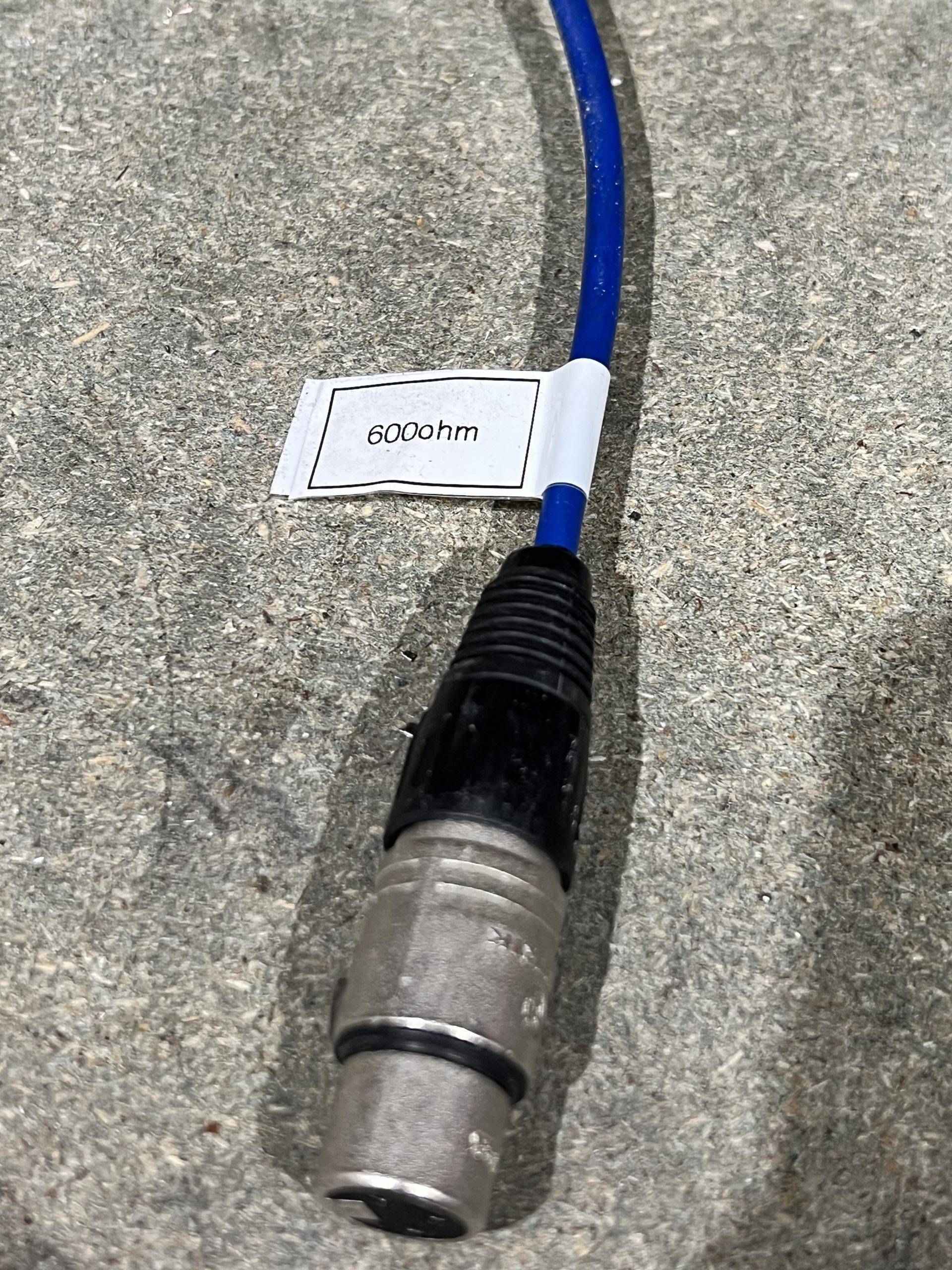
To do this all you need is a short XLR to XLR such as the one in the picture below.
Solder the chosen resistor across PIN 2 and PIN 3 of the XLR.
See picture below.

Close the XLR connector back together, add a label so you do not get confused with other cables and install it at the output of the 600 ohm device you want to use it on. Job done!
